AXI_IIC读写操作
其实在之前调试过一次AXI_IIC,没调试通,碍于赶进度,就直接使用了zynq-PS侧的IIC,就一直搁置着了,这次抽空将这部分内容继续调试下去,这一次没花多少时间就调通了,现在将我的调试过程,经历,以及参考文档如下:参考文档:pg090-axi-iic.pdf参考链接:https://forums.xilinx.com/t5/Design-and-Debug-Techniques-Blog/II
其实在之前调试过一次AXI_IIC,没调试通,碍于赶进度,就直接使用了zynq-PS侧的IIC,就一直搁置着了,这次抽空将这部分内容继续调试下去,这一次没花多少时间就调通了,现在将我的调试过程,经历,以及参考文档如下:
参考文档:pg090-axi-iic.pdf
参考链接:https://forums.xilinx.com/t5/Design-and-Debug-Techniques-Blog/IIC-Protocol-and-Programming-Sequence/ba-p/1072248
上面的这个参考链接是很值得参考的,相较于直接看pg090还是简练了不少。
工程搭建没有什么特别的,提供一张搭建完成的block_design(外设我这里挂载包括,qspi,mig,uart,iic,这里其实只需要uart,iic即可):
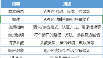
这里我们在使用IP时先了解一下IP中的寄存器(因为我没有使用中断,这里我们只用到了CR,SR,TX_FIFO,RX_FIFO,TX_FIFO_OCY):
然后就是sdk程序了,这里我先将程序贴出来:
#include <stdio.h>
#include "platform.h"
#include "xil_printf.h"
#include "xparameters.h"
#include "xil_io.h"
#include "sleep.h"

#define GIE 			0x01c
#define ISR 			0x020
#define IER				0x028
#define SOFTR			0x040
#define CR				0x100
#define SR				0x104
#define TX_FIFO			0x108
#define RX_FIFO			0x10c
#define ADR				0x110
#define TX_FIFO_OCY		0x114
#define RX_FIFO_OCY		0x118
#define TEN_ADR			0x11c
#define RX_FIFO_PIRQ	0x120
#define GPO				0x124

#define IIC_Device_ID   0x50

void Initialization_IIC();
void Single_Byte_Write(u8 Device_ID, u8 high_8bit_Address,u8 low_8bit_Address,u8 data);
u8 Single_Byte_Read(u8 Device_ID, u8 high_8bit_Address,u8 low_8bit_Address);

int main() {
	u8 Received_data;
	u8 flag=0;
	init_platform();

	Initialization_IIC();
	for(int i=0;i<8192;i++){
	Single_Byte_Write(IIC_Device_ID,i>>8,i,i);
	if(i%1024==0)
	xil_printf("%d\n\r",i);}

	for(int i=0;i<8192;i++){
	Received_data = Single_Byte_Read(IIC_Device_ID,i>>8,i);
	xil_printf("Received:%x\n\r",Received_data);
	if(i%256 != Received_data)
		flag=1;
	}

	if(flag == 1)
		xil_printf("Received data is not correct.Test failed.\n\r");
	xil_printf("Test finish.\n\r");
	cleanup_platform();
	return 0;
}

/**********************************************************************************************/
//	Initialization
//		1.Set the RX_FIFO depth to maximum by setting RX_FIFO_PIRQ = 0x _ _
//		2.Reset the TX_FIFO with 0x_ _
//		3.Enable the AXI IIC, remove the TX_FIFO reset, and disable the general call
//  Parameter:
//		None.
//	Return:
//		None.
void Initialization_IIC() {
		Xil_Out32(XPAR_AXI_IIC_0_BASEADDR + RX_FIFO_PIRQ, 0x0000000f);//Set the RX_FIFO depth
		Xil_Out32(XPAR_AXI_IIC_0_BASEADDR + CR, Xil_In32(XPAR_AXI_IIC_0_BASEADDR + CR)|0x00000002);//Reset the TX_FIFO
		Xil_Out32(XPAR_AXI_IIC_0_BASEADDR + CR, Xil_In32(XPAR_AXI_IIC_0_BASEADDR + CR)|0x00000001);//Enable the AXI IIC
		Xil_Out32(XPAR_AXI_IIC_0_BASEADDR + CR, Xil_In32(XPAR_AXI_IIC_0_BASEADDR + CR)&0xfffffffd);//Remove the TX_FIFO reset
		Xil_Out32(XPAR_AXI_IIC_0_BASEADDR + CR, Xil_In32(XPAR_AXI_IIC_0_BASEADDR + CR)&0xffffffbf);//Disable the general call
		xil_printf("Initialization_IIC Device finished.\n\r");
}

/**********************************************************************************************/
//	Write Bytes to an IIC Slave Device Addressed as 0x_ _
//	Place the data at slave device address 0x__:
//		1.Check that all FIFOs are empty and that the bus is not busy by reading the SR
//		2.Write 0x___ to the TX_FIFO (set the start bit, the device address, write access)
//		3.Write 0x__ to the TX_FIFO (slave address for data)
//		4.Write 0x__ to the TX_FIFO (byte 1)
//		5.Write 0x__ to the TX_FIFO (byte 2)
//		6.Write 0x__ to the TX_FIFO (stop bit, byte x)
//  Parameter:
//		Device_ID:0x01010,A2,A1,A0
//		high_8bit_Address:first word address
//		low_8bit_Address:second word address
//		data:8bit send data
//	Return:
//		None.
void Single_Byte_Write(u8 Device_ID, u8 high_8bit_Address,u8 low_8bit_Address,u8 data){
	while((Xil_In32(XPAR_AXI_IIC_0_BASEADDR + SR) & 0x000000C4) != 0x000000c0) {}//Check that all FIFOs are empty and that the bus is not busy by reading the SR
	Xil_Out32(XPAR_AXI_IIC_0_BASEADDR + TX_FIFO, (Device_ID<<1)|0x00000100);//Write 0x___ to the TX_FIFO (set the start bit, the device address, write access)
	Xil_Out32(XPAR_AXI_IIC_0_BASEADDR + TX_FIFO, high_8bit_Address);//Write 0x__ to the TX_FIFO (slave address for data)
	Xil_Out32(XPAR_AXI_IIC_0_BASEADDR + TX_FIFO, low_8bit_Address);//Write 0x__ to the TX_FIFO (slave address for data)
	Xil_Out32(XPAR_AXI_IIC_0_BASEADDR + TX_FIFO, data|0x00000200);//Write 0x__ to the TX_FIFO (stop bit, byte 1)
	usleep(100000);
}

/**********************************************************************************************/
//	Read Bytes from an IIC Device Addressed as 0x_ _
//		1.Check that all FIFOs are empty and that the bus is not busy by reading the Status register
//		2.Write 0x___ to the TX_FIFO (set the start bit, the device address, write access)
//		3。Write 0x__ to the TX_FIFO (slave address for data)
//		4.Write 0x__ to the TX_FIFO (slave address for data)
//		5.Write 0x___ to the TX_FIFO (set start bit, device address to 0x__, read access)
//		6.Write 0x___ to the TX_FIFO (set stop bit, four bytes to be received by the AXI IIC)
//		7.Wait until the RX_FIFO is not empty.
//	a) Read the RX_FIFO byte.
//	b) If the last byte is read, then exit; otherwise, continue checking while RX_FIFO is not empty.
//  Parameter:
//		Device_ID:0x01010,A2,A1,A0
//		high_8bit_Address:first word address
//		low_8bit_Address:second word address
//		data:8bit send data
//	Return:
//		8bit Recevived data.
u8 Single_Byte_Read(u8 Device_ID, u8 high_8bit_Address,u8 low_8bit_Address){
	u8 Received_data;
	while((Xil_In32(XPAR_AXI_IIC_0_BASEADDR + SR) & 0x000000C4) != 0x000000c0) {}//Check that all FIFOs are empty and that the bus is not busy by reading the Status register
	Xil_Out32(XPAR_AXI_IIC_0_BASEADDR + TX_FIFO, (Device_ID<<1)|0x00000100);Write 0x___ to the TX_FIFO (set the start bit, the device address, write access)
	Xil_Out32(XPAR_AXI_IIC_0_BASEADDR + TX_FIFO, high_8bit_Address);//Write 0x__ to the TX_FIFO (slave address for data)
	Xil_Out32(XPAR_AXI_IIC_0_BASEADDR + TX_FIFO, low_8bit_Address);//Write 0x__ to the TX_FIFO (slave address for data)
	Xil_Out32(XPAR_AXI_IIC_0_BASEADDR + TX_FIFO, (Device_ID<<1)|0x00000101);//Write 0x___ to the TX_FIFO (set start bit, device address to 0x__, read access)
	Xil_Out32(XPAR_AXI_IIC_0_BASEADDR + TX_FIFO, 0x00000200);//Write 0x___ to the TX_FIFO (set stop bit, four bytes to be received by the AXI IIC)
	while((Xil_In32(XPAR_AXI_IIC_0_BASEADDR + SR) & 0x00000040) == 0x00000040) {}//Wait until the RX_FIFO is not empty.
	while((Xil_In32(XPAR_AXI_IIC_0_BASEADDR + SR) & 0x00000040) != 0x00000040){
		Received_data = Xil_In32(XPAR_AXI_IIC_0_BASEADDR + RX_FIFO);
	}
	return Received_data;
}
操作流程上面完全按照上面的链接操作的,所有的操作都在注释信息中标的很清楚,我的EEPROM(24C64) A0,A1,A2均接的GND(器件地址0x50),里面有(64Kb的地址空间,全部访问需要13位,所以有16位地址)。
注意事项:
1.我的代码是单字节的读写。
1.我们在做读操作时,设置stop时,后面紧跟着的8位表示要接收几Byte的数据,0代表0,1代表1,2代表2,以此类推,我没有写错,0特殊
2.如果对同一个地址空间先写后读,中间一定要间隔0.01s以上,不然你读回来的数据都是FF。
3.如果对不同的地址进行连续的单字节写,中间也一定要间隔0.01s以上,不然你会发现写两个Byte就卡住了。
4.Page的读写操作,和这个类似,但一定要注意访问时间的间隔问题(我没试过Page读写)。
5.前面三个问题,我查找各种状态位做判断都不起作用,如果有人发现其他好的解决办法可以告我一声。
6.调试时可以尝试抓取IIC的信号,scl_i/o/t,sda_i/o/t,注意采样深度,我的是20M时钟采样65536个周期才能看到完整的读写。
7.我上述的代码,光写操作就花费将近15分钟时间,scl 100K,好慢啊.
签名:20201029 olivercao 著

有“AI”的1024 = 2048,欢迎大家加入2048 AI社区
更多推荐
 20
20 0
0- 0


 已为社区贡献2条内容

所有评论(0)